Category: Media Gallery
Multivariate Visualization
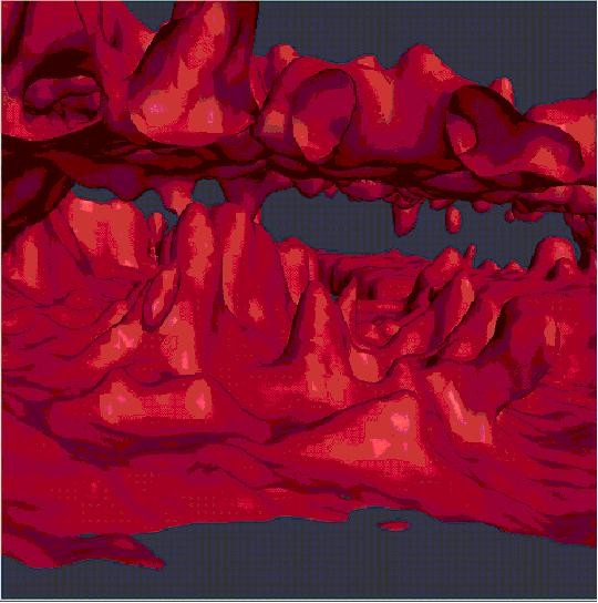
Isosurface of Flourescence
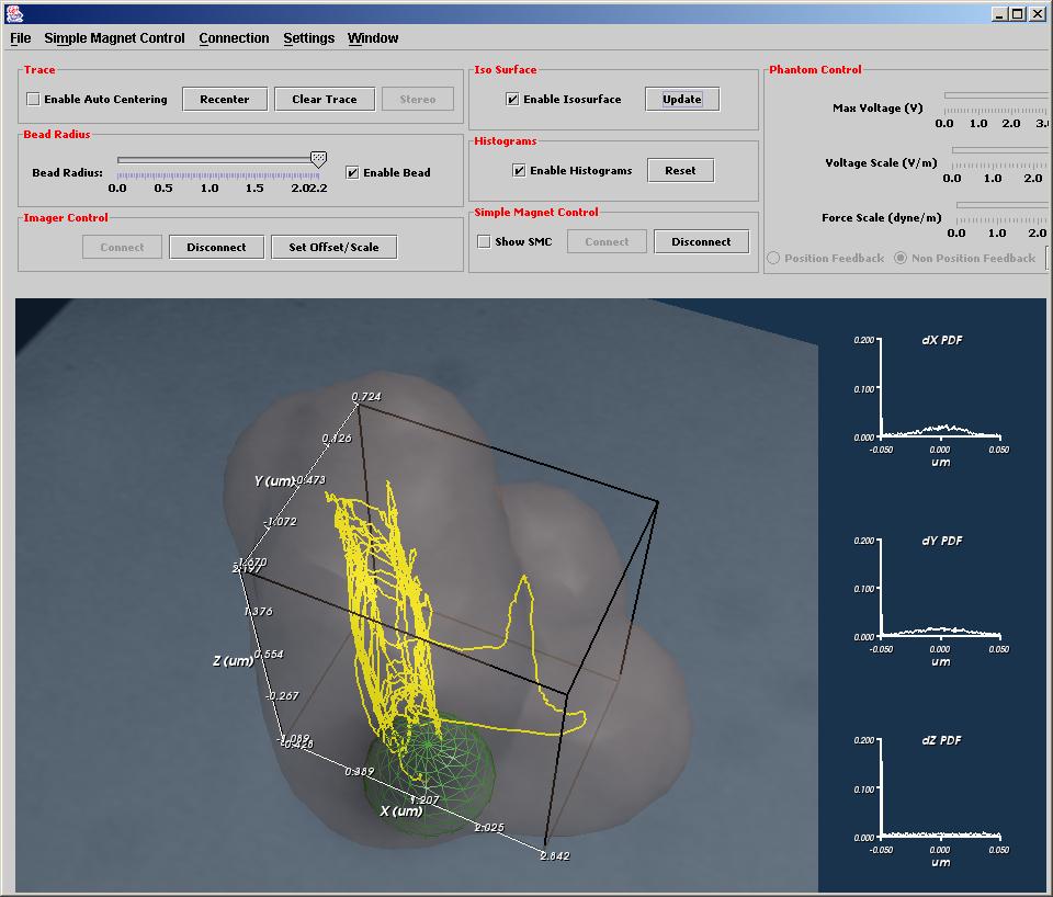
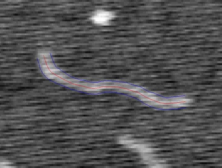
A Tracked Strand of DNA
TEM Simulator Movie
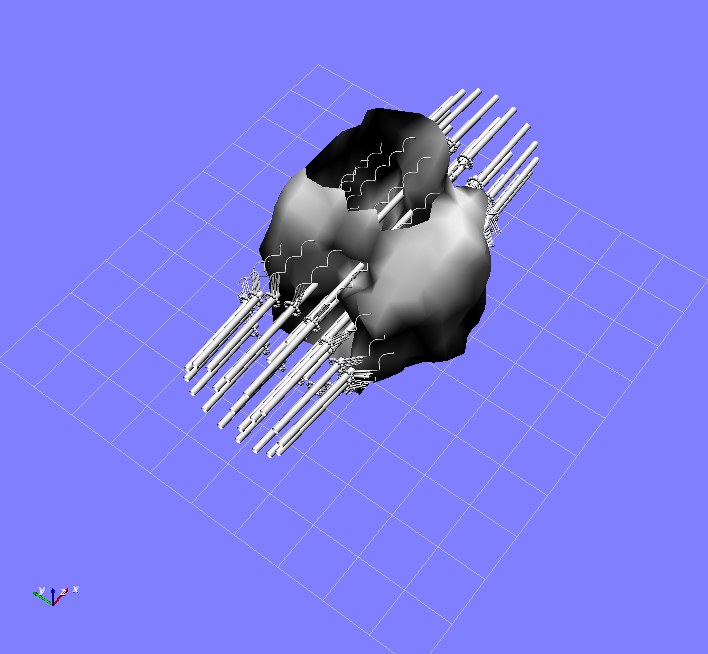
This is a movie of a TEM simulation of curved single wall nanotube being moved over an amorphous carbon background. It runs at 12 fps.
This is a longer version of the same movie. Both movies were made using a graphics-hardware-accelerated simulator produced by David Borland as part of our accelerated microscope simulation and analysis work. The curved nanotube shown in the video is moved by hand using a 6-degree-of-freedom manipulation device while the background thickness is adjusted. The combined background + tube simulation is run at 12 frames/second.
3DFM NanoRod Bead Vortex
This clip starts with a bead being positioned near a nanorod using a laser trap. Then, an orbit is applied to the rod using the magnets of the 3DFM and it starts to beat. A flow in the CCW direction is created, and the bead can be seen to flow around the rod. Then, the beat frequency is doubled, and the bead’s orbital radius increases.
NanoRod Stands on End in 3DFM
In this clip, we start with a NanoRod flat on the substrate, and are able to use the magnets to get the rod to stand up vertically on the coverslip. We then apply an orbitting voltage, and watch the rod’s tip move in a square-like orbit.
Perfect Orbit
We observe a magnetic bead with a 4.4-micron diameter being pulled around by the four poles of the initial “”Betty”” setup of our 3DFM. The bead is in a corn-syrup solution with a calibrated viscosity of 86 centiPoids. The video shows two complete orbits of the bead, as it is pulled towards each magnet in turn.
3DFM Concept Video
A fanciful view inside a cell intended to show the concept of the 3DFM. It starts with a view of several microtubules and follows the motion of a bead along one of them. As it zooms in, we can see a representation of a kinesin walking its way along the microtubule, carrying the bead. Using the 3DFM, we hope to be able to track, stall, and measure the forces on kinesin and other motor proteins as they perform their duties within living cells.
