
Mitotic Spindle under Brownian Motion

August 24, 2012

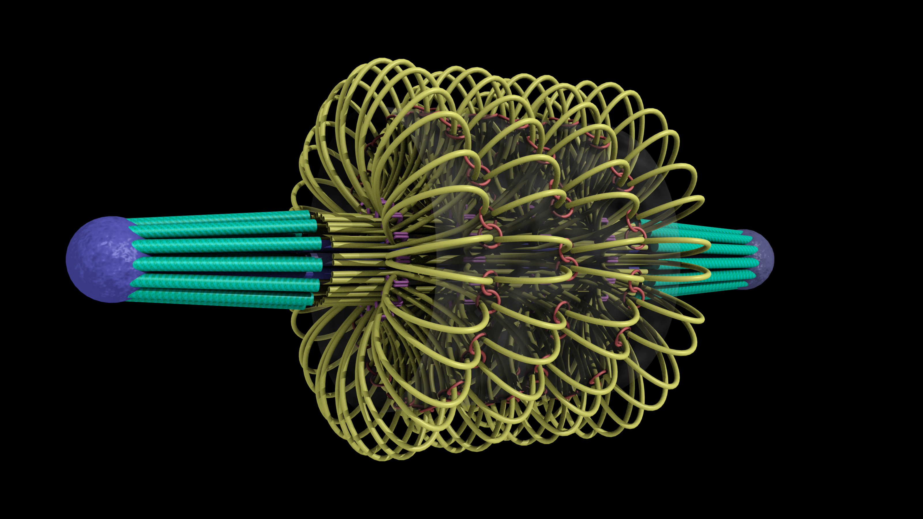
A model of the yeast mitotic spindle in metaphase was constructed based on a looping model of DNA distribution, where the loops are tied together at their base by condensin and they are linked by slip-rings of cohesin.    This model was created in collaboration between Kerry Bloom and his group and CISMM personnel.  The geometry of the model at its initial state is shown below.

brownian_yeast_initial_condition

The code was developed by Belinda Johnson.  A coarse-grained simulation was run, based on the SOFA platform with the addition of Brownian forces and stiffness forces, to understand what the addition of Brownian forces on the structure would do to the distribution of DNA.  The parameters of the simulation included a random force of 1228, a mass_damping of 10, a mass_radius of 0.0045, a spring constant of 628000, a hinge force of 0.548, and an object mass of 33.3 (see simulation code for the units).  We believe that this model matches the expected behavior except for: (1) the viscosity is much lower than in reality so that the simulation will run in reasonable time (we expect the behavior to be the same).  (2) The cohesin rings are too large by about a factor of two (this was a mistake in the model set up, which we think will only serve to make the rings more mobile).  (3) There is no torsional restoring force on the DNA, so there will be no impact due to twisting of the DNA strands.

The resulting movie of the simulation is available here: 0001-0167.  It shows a snapshot of the simulation every 0.1 nanoseconds up to 17.6 nanoseconds.

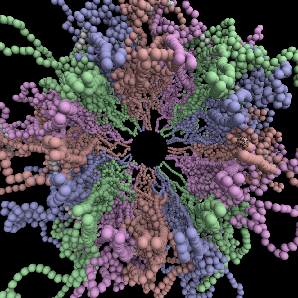
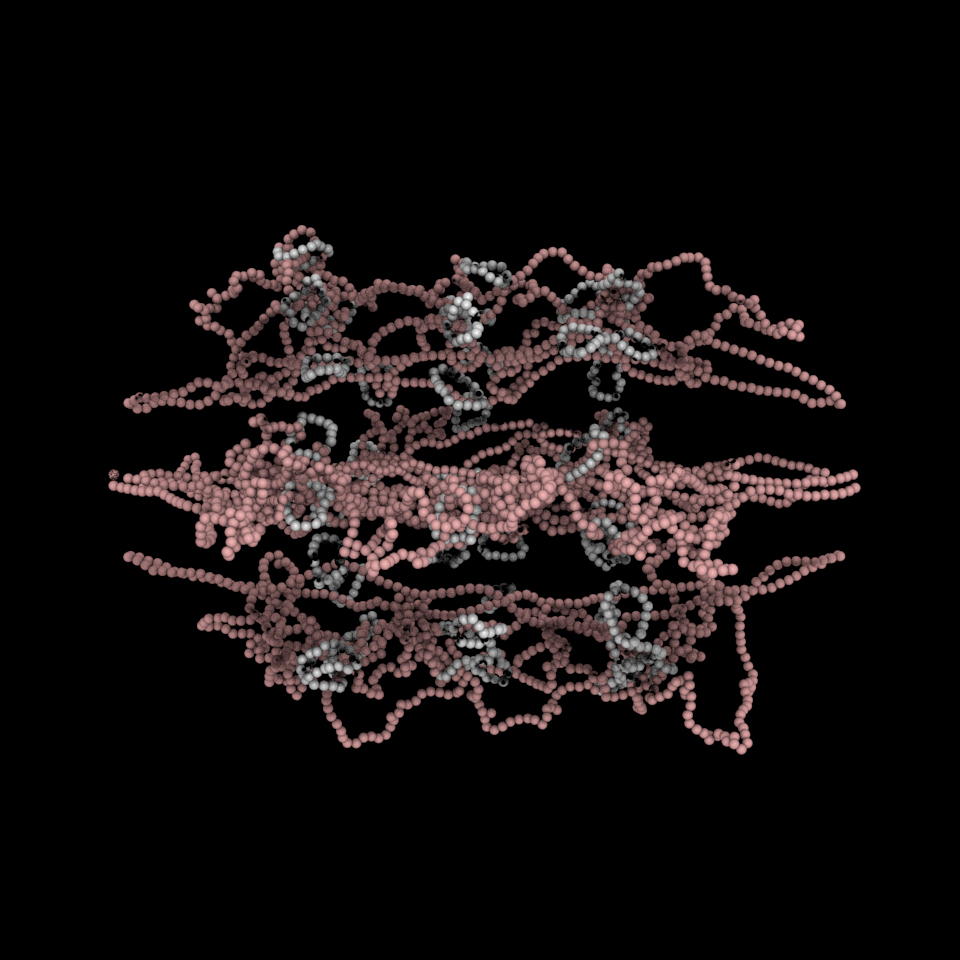
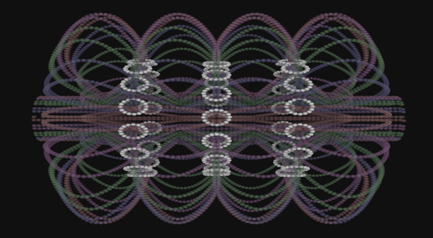
The simulation showed the outside of the rings pulling in and the inside of the spindle pushing out.  There was not a large net offset to the cohesin rings from their initial position (each moves, but they seem to maintain their approximate position).  The ends of the DNA are pinned in space as if to stable microtubules. Some images of the resulting configuration are shown below.

OUTFILE3_v2_endview

OUTFILE3_v2_side_four_sisters

Yeast Mitotic Spindle

May 11, 2011

The image below is a proposed structure for the mitotic spindle of yeast during metaphase that was produced in a collaboration between Russell M. Taylor II, Andrew Stephens, Kerry Bloom, Leandra Vicci, Jolien Verdaasdonk, Steven Nedrud, Matt Larson, and Michael Falvo.

cismm_entry_science_contest_brighter

Others participated in the earlier development of the model, including Kendall McKenzie and Callie Holderman.

This model of the yeast mitoric spindle shows the spindle-pole bodies as blue spheres, the kinetochore microtubules as green cylinders, the DNA as yellow tubes, cohesin as linked red rings, and condensin linking molecules in purple.  The translucent gray shell around the spindle shows the center of the region that contains cohesin as seen in fluorescence microscopy images taken of the spindle.  The DNA and other structures are too small to be resolved in the microscope.  This is the twentieth version of the model, which has been developed over a two-year period of intense collaboration between cell biologists, computer scientists, physicists, and artists.  This was developed as part of the Computer-Integrates Systems for Microsopy and Manipulation NIH/NIBIB National Research Resource.

It is a geometric model of a hyopthetical structure that has evolved to be consistent with a number of experiments performed in the department of Biology.  Its purpose is to display, in a consistent 3D space, a model, all known aspects of the structure.  This forms a basis for discussion, which then results in new planned experiments and in changes to the model.

This image was an honorable mention in the illustration category of the NSF/Science visualization challenge 2010.

About the yeast: The yeast is Saccharomyces cerevisiae as used for baking and brewing. The strains we use are science based versions not commonly used for brewing or baking, but they are the same species.  S cerevisiae is one of the most commonly used eukaryotic model systems in biology.

Mitotic Spindle 3D Model Zoom

August 12, 2009
3D Spindle Model Close-up

This is an image of Kendall McKenzie’s 3D model of the mitotic spindle made in Maya rendered from a zoomed-in perspective.

Mitotic Spindle Cross Section

July 23, 2009

This drawing shows a cross section of the mitotic spindle, with a diameter of 250 nm.  The 16 kinetochore microtubules are green, the 8 interpolar microtubules are orange, and the strands of DNA are represented by purple squiggly lines

Close-up Drawing of DNA Structure

July 23, 2009
This drawing shows the form DNA takes when it is between the microtubule (green) end and a gap from which a loop extends. The microtubule is attached to the DNA by the kinetochore structure (pink), which is 80 nm long. The kinetochore attaches to the DNA (yellow) at a hook-like space near the cse4 nucleosome (shown at the end). There are 55 histones (orange) on each of the "top" and "bottom" of the structure. Roughly 75% of the length of the DNA strand is tangled in "loop" structures, and the other 25% is between loops in a straighter line. Condensin (blue) binds to the DNA at the bottoms of the loops. Condensin (purple) wraps around and encloses the DNA within the loops and where there is a space on the far right. The small green asterisks show where the GFPs are placed on cohesin and condensin in the lab.
This drawing shows the form DNA takes when it is between the microtubule (green) end and a gap from which a loop extends. The microtubule is attached to the DNA by the kinetochore structure (pink), which is 80 nm long. The kinetochore attaches to the DNA (yellow) at a hook-like space near the cse4 nucleosome (shown at the end). There are 55 histones (orange) on each of the “top” and “bottom” of the structure. Roughly 75% of the length of the DNA strand is tangled in “loop” structures, and the other 25% is between loops in a straighter line. Condensin (blue) binds to the DNA at the bottoms of the loops. Condensin (purple) wraps around and encloses the DNA within the loops and where there is a space on the far right. The small green asterisks show where the GFPs are placed on cohesin and condensin in the lab.

Mitotic Spindle

July 23, 2009
This drawing shows the spindle from end to end.  It is roughly 1.5 micons in length, with the kinetochore (green) microtubules making up 350 nm on each end, and the space between them being roughly 800 nm.  The interpolar microtubules are drawn in two shades different shades of purple (dark purple ones extend from the left end of the spindle and pink-purple ones extend from the right end of the spindle).  The microtubules are drawn straight and rigid, with an overall spindle diameter of 250 nm.   Also, the DNA strands (yellow) extend even more outwardly than the microtubules.  The two outermost strands of DNA (top and bottom of the spindle) have a few loops of DNA drawn in to show that the diameter of the spindle reaches 400 nm when the loops are included.  Each of the other strands has a small break in it that represents a place where extra loops of DNA are attached.  They are not drawn because they would make the details of the spindle hard to see. The bottom right corner shows the layout and packing of the microtubules at the spindle pole, not in a "convergence point" formation, but in a more tightly packed formation that has a diameter of 150 nm.
This drawing shows the spindle from end to end. It is roughly 1.5 micons in length, with the kinetochore (green) microtubules making up 350 nm on each end, and the space between them being roughly 800 nm. The interpolar microtubules are drawn in two shades different shades of purple (dark purple ones extend from the left end of the spindle and pink-purple ones extend from the right end of the spindle). The microtubules are drawn straight and rigid, with an overall spindle diameter of 250 nm. Also, the DNA strands (yellow) extend even more outwardly than the microtubules. The two outermost strands of DNA (top and bottom of the spindle) have a few loops of DNA drawn in to show that the diameter of the spindle reaches 400 nm when the loops are included. Each of the other strands has a small break in it that represents a place where extra loops of DNA are attached. They are not drawn because they would make the details of the spindle hard to see. The bottom right corner shows the layout and packing of the microtubules at the spindle pole, not in a “convergence point” formation, but in a more tightly packed formation that has a diameter of 150 nm.

Kinetochore Drawing

July 23, 2009
This drawing shows the structure of the kinetochore. A microtubule (green) with a flared end is surrounded by 8 thin rods/proteins (blue), which are then enclosed by 16 proteins (pink). This structure then connects (in a way that is not shown) to the DNA strand (yellow) while it is in a hook-like structure holding the cse4 nucleosome.


Chromatin in the Nucleus

July 23, 2009

This drawing shows the packing of the chromatin (orange) in the nucelus.  The microtubules (green) extend out both sides of the nuclear membrane, and the chroma

This drawing shows the packing of the chromatin (orange) in the nucelus.  The microtubules (green) extend out both sides of the nuclear membrane, and the chromatin is bunched/tangled up inside the nucleus.  The round nucleus is about 1.5 microns in diameter.
This drawing shows the packing of the chromatin (orange) in the nucelus. The microtubules (green) extend out both sides of the nuclear membrane, and the chromatin is bunched/tangled up inside the nucleus. The round nucleus is about 1.5 microns in diameter.

tin is bunched/tangled up inside the nucleus.  The round nucleus is about 1.5 microns in diameter.

Mitotic Spindle 3D model overview

April 12, 2009
3D Spindle Model Overview

This is an image of Kendall McKenzie’s 3D model of the mitotic spindle made in Maya rendered from an overview perspective.