Template-Based Matching Tutorial: Dimer Proteins
The CISMM Template-Based Matching program is designed to locate and identify objects within Scanned-Probe Microscope images and produce a file of descriptive statistics about these objects. This tutorial describes how to determine the best-matching templates for a set of dimers on a surface scanned by an AFM.
Data Set

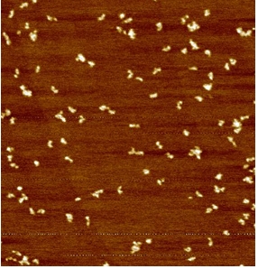
Included in the Example_data directory is an image from Dorothy Erie’s laboratory of MutL dimers (two proteins attached).
When the program first runs, it asks for a data file to open; the file is in the Example_Data directory and is named erie_protein_example_JH120704.019.
Recommended Analysis Procedure
For this example, the three red ‘+’ signs that indicate the coordinates to flatten the image based on are all located on the substrate, so they do not need to be moved. However, you can move them around using the left mouse button if you want. Notice that the image in the Flattened window will adjust slightly while you do this.

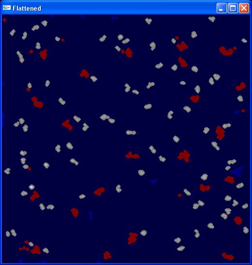
To select which objects should be considered as candidate dimers, adjust the height_threshold and Volume Thresholds values. A lower volume threshold of around 0.08 and an upper of about 0.37 will remove the objects in the image that are too large or too small. The default height threshold of 0.4 works well for this example.
To prevent clipping of the volume estimation, increase the dilation value to 2.
At this point, the Flattened image should look like the image to the right. This completes the image-adjustment portion of the process; now we’re ready to select templates to match against.
It is possible to construct analytic templates for objects to be found, but for this example we will select examplar features from the image itself. Click with the mouse on one of the objects in the Flattened image that is long and skinny, like the one near the very center. When you do, a dialog box will appear asking for the name of the template. Go ahead and type the name ‘straight’ and hit enter. A new small image will appear below the original image that shows the template you have selected. Click on a round, compact object in the image and named it ‘compact’. Finally, pick one that is bent at nearly 90 degrees and name it ‘bent’.
So that it will be easier to tell which object described in the resulting data file matches each object on the screen, select the show_labels check-box. We will stick with the coarse alignment parameters that are the defaults for the angle_step and pixel_step. For a more precise fit, an angle step of 5 degrees and a pixel step of 1 are better, but this will take a long time to compute.
We’re ready to perform our fitting by pressing the Save button at the bottom of the control panel. This will bring up a dialog box asking where to save the Comma-Separated Value (CSV) file that will hold our results. Select the Desktop folder to put it in, type the name deleteme and then hit enter. A progress box will appear briefly and a file named ‘deleteme.csv’ will appear on the desktop.
You can open deleteme.csv using Excel, OpenOffice, Matlab, or even Wordpad to look at its contents. The first few columns report the object ID (matching the label shown in the Best Fit image), the center of mass (x,y), and the volume above background for the object. (These will appear even if you don’t select any templates — the program can be used just to calculate them if you like.) Next come two descriptions, one for the best-fit template and another for the next-best fit (so you can see how specific the fit is). Each includes the error between the template and the actual object and the angle at which the template fits best.